Arduino Components
- LED's
Wiring And Basic Tutorial for Mobiflight & Prosim using Ardunio Mega

When using simulators, it's incredibly satisfying to receive instant feedback from a virtual cockpit indicator through an illuminated LED in real life. This realization sparked my desire to elevate my SIM experience to new heights.
Starting with the PMDG 737 parking brake, I've now incorporated hundreds of LEDs into my SIM with the license plate number 737 DIY. These LEDs come in various sizes and colours, including Bi and tri-colour options for AFDS lights that require both yellow and red in a single bulb. I primarily use 3mm and 5mm LEDs, choosing warm white for panel backlighting to create a more realistic feeling. However, bright white works just as well. It's important to always use a resistor with the LED from the Arduino board.
LED - Leg Layout

The first thing you need to know about light-emitting diodes (LEDs) is that they are polarity-sensitive. Two legs extend from the LED body. These are called the Anode and Cathode.
The cathode (-) must be connected to the ground of the Arduino. The anode (+) must be connected to pins 2-53 on the Arduino.
To distinguish between the legs, they have the following features:
The cathode leg is next to the side with the flat side on the body. This leg is shorter.
The anode is the longer leg.
RESISTORS - A MUST!
As previously mentioned, it is necessary to use a resistor in conjunction with most LEDs. Unlike LEDs, resistors are not polarity-sensitive and can be installed in any direction. A general guideline for Arduino use is to utilize a 120-ohm resistor.
Typically, a standard LED functions within the range of 2-3Vdc. On the other hand, the Arduino operates at 5V. The resistor serves to restrict the current supplied to the LED. While it is possible to occasionally connect an LED without a resistor, the LED will not last for long. LEDs are usually designed to run on a current of 20mA, which will produce a very bright light.

The brightness can be set by using different value resistors. Sometimes, if flying at night, you might find that 120 Ohm resistors are still too bright, especially if you purchase ultra-bright clear LEDs. These can be replaced with 220 Ohm resistors to dim the LED to half brightness.
Many online resistance/LED calculators can help you find the correct value. My favourite is:
https://www.hebeiltd.com.cn/?p=zz.led.resistor.calculator
The colour code of a 220 Ohm resistor is:
Red, Red, Brown and a gold tolerance band of (5%)
LED - WIRING

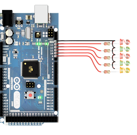
Connecting an LED is a straightforward process. The Cathode, which is the shorter leg on the flat side, should be connected directly to the ground of the Ardunio. It doesn't matter which wire the resistor is attached to, but I personally prefer to keep it on the anode side, which goes to the Ardunio pin (2-53). If you use one of the PWM pins, you can adjust the brightness of the LED through software (Remember to use a resistor). There are different ways to attach the resistor, but I typically solder it inline or use a breakout board with resistors placed inline.
LED's - 2 OR MORE
On each board, it is possible to add up to 40 LEDs. For the purpose of simplifying the diagrams, I have only displayed 5 LEDs. However, the concept remains the same. The ground is daisy-chained in order to reduce the amount of wiring needed to connect back to the Arduino. Due to the possibility of the looms becoming quite large (containing 52 wires), this method helps to keep the size to a minimum.

LED's & Switches - Multiple Devices
When combining LEDs and switches, daisy-chain the grounds and send all wires to the Arduino Pins. The specific pins used do not matter.

LEDs with Switches - Tactile LEDs with Wiring Diagrams
When building simulators, tactile LED switches are a fantastic choice. These switches allow for the creation of custom buttons that light up and can be pressed. They come in various colours and two main types: a 12mm square version and a much smaller 6mm version, which I typically use in my panel designs. Regardless of type or colour a resistor must be used. All my LED tactile switches typically have a red mark on the cathode side.


Colour
Green
Yellow
Orange
Red
Blue
White
OP V
3.05v
2.06v
1.97v
1.98v
3.02v
3.00v
Resistor
100 Ohm
150 Ohm
180 Ohm
180 Ohm
100 Ohm
100 Ohm
For reference, I have measured the forward bias of the 6x6mm tactile LED switches. When using the Arduino 5v, supply at the recommended maximum current of 20mA.
You can run the LEDs at a higher current. They will be brighter, but their operating life will be drastically shorter. Most people find that 20 mA is usually too bright and up the resistor value to dim the LED. This is down to personal preference.