top of page

Bell 212 Heli Cyclic

This page is split into three main sections:

Parts Guide

Print Guide

Build Guide

The ultimate printer I can recommend is the Bambu Labs X1 carbon with AMS or P1P if you have deep pockets. ($1200). It's a massive leap forward in 3D printing, with excellent quality and impressive speeds. It's pretty much press print and go as the software and hardware do the calibration before each print. 

pilot sign get here.png
737 SINGLE YOKE HEAD.jpg

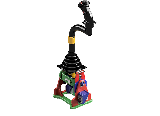
This has to be one of my favourite designs to date. After working on helicopters for over 28 years, I often wondered how to reproduce the controls to make them realistic. The hardest part that any Helipilot has tried is to replicate the magnetic clutch.

I have used a stepper motor (standard Nema 17) as the mag brake, Parallel actuator, Beep trim and later on the autopilot drive unit (series Actuator).

This is NOT a force-feedback unit because helicopters do not operate like that. The control rods/cables are typically connected to servos. Due to the astronomical forces required to move the controls (between 3-20 tonnes), there are no feedback forces through the servos/controls. This is usually done by linear force feel units (springs) acting on a parallel actuator which can reset the datum point at any position. This is the purpose of the Stepper motor in this case. Most modern twin-engined rotorcraft are uncontrollable if full hydraulic servo power is lost.

This system replicates the Bell 212 cyclic forces with force trim in. Most pilots I know on the 212 like to hover, take off and land with force trim off. This makes the cyclic go completely floppy and makes controlling the aircraft easier for more extended periods of time, such as winching.

To increase the force of the cyclic, stronger springs can be added to the force feel units for those preferring a more robust resistance feel. The forces this particular cyclic replicates is that of the Bell 212HP.

This unit comes with the following:

1) A trim release switch beep trim top hat.

2) A cargo release button (not used yet but is connected).

3) An ICS/Transmit dual point trigger (not connected)

4) AFCS release button (Connected but not used yet)

At the moment, The cyclic can be repositioned in any neutral position using the trim release. Once the button is released, the cyclic will hold that position and force feel is enabled. Fine-tuning the cyclic position electrically can be used by trimming the Beep switch top hat in the direction required.

I have included a highly detailed Bell 212 cyclic grip. If you have a resin printer, I recommend using this for a smooth finish. For those that do not have access to a resin printer, I might be able to produce them for you at a cost, but this will be a limited quantity due to the time they take.

Please note: I have made the cyclic fitting 25mm so it will fit most aircraft grips, both rotary and fixed-wing. So if you have another type, it should be interchangeable.

There is no complicated software involved, just Mobiflight, and I soon hope to issue the exact file, so you do not have to programme anything. This unit replicates a standard PC joystick, using a Leo Bodnar card to keep things simple. This means it can be used on XP, DCS, P3D and MSFS!

I hope this puts a smile on your face like it did so many at the EXPO in Lelystad, including real-life pilots!

Pre-release right now while I construct the Build/Print and parts guide, which will be added here (if you want to start printing:

The build guide and components list can be found here:

https://www.737diysim.com/build-guides-1/bell-212-heli-cyclic

General Information:

Pilot Spanner.jpg

Build Guide

737_YOKE_CONTROL_HEAD_single_2020-Oct-31
Click on image for more details
737_YOKE_CONTROL_HEAD_single_2020-Oct-31
Click on image for more details

STEP:

2

Insert the #d printed Sweepback (C3) into the 40mm diameter PVC pipe. I used a PVC pipe with a length of 260mm. The height will be dependent on your setup. You want the base of the cyclic grip to be about 1" from the top of your thighs when seated.

737_YOKE_CONTROL_HEAD_single_2020-Oct-31
Click on image for more details

STEP:

3

Slide the (Z1) drill guide over the PVC pipe. Ensure the PVC pipe and sweepback parts are firmly pressed together. Also, ensure the 'F' is facing forward, away from the 3d printed sweepback part. Once the drill guide is located, use a 4.0mm (4.3mm to be precise) to drill the four marked orifices gently. Just drill enough to mark the location on the PVC pipe lightly. Remove the sweepback part and then drill through the guide. This way, you will not oversize the screw holes in the sweepback part.

737_YOKE_CONTROL_HEAD_single_2020-Oct-31
Click on image for more details

STEP:

4

Inset QTY 4, M4 x 8mm Screws into the parts to firmly secure them together.

737_YOKE_CONTROL_HEAD_single_2020-Oct-31
Click on image for more details

STEP:

5

Insert the wire loom through the parts and feed the cyclic grip onto the cyclic tube.

737_YOKE_CONTROL_HEAD_single_2020-Oct-31
Click on image for more details

STEP:

6

Insert an M5 locknut into the Cyclic grip body on the LHS.

737_YOKE_CONTROL_HEAD_single_2020-Oct-31
Click on image for more details

STEP:

7

Insert an M5 x 55mm Socket head screw into the RHS of the cyclic grip and gently tighten the grip until it's secure on the assembly.

737_YOKE_CONTROL_HEAD_single_2020-Oct-31
Click on image for more details

STEP:

8

Place the boot (B2) onto the base of the cyclic tube. This part is optional. Printing TPU can be awkward and difficult.

737_YOKE_CONTROL_HEAD_single_2020-Oct-31
Click on image for more details

STEP:

9

Insert Qty 2, 6203 bearings into the Unilever Base (U1)

737_YOKE_CONTROL_HEAD_single_2020-Oct-31
Click on image for more details

STEP:

10

Place the drill guide (Z2) on the cyclic tube. Place both the tube and drill guide onto the Unilever base. Ensure the parts are firmly pressed together. Once again, gently drill the parts with an 8.2mm drill bit. This time you can drill through all parts.

737_YOKE_CONTROL_HEAD_single_2020-Oct-31
Click on image for more details

STEP:

11

Cut a piece of 8mm threaded rod to at least 105mm in length. Ensure the drill guide Z2 is removed and insert the rod through the pieces. Remember to add a chamfer with a file to the ends of the threads. This allows the threads to receive the nut again after cutting. Alternatively, you can place nuts onto the part to be cut. Once the threaded rod is cut, screw the nuts off each end to restore the threads.

737_YOKE_CONTROL_HEAD_single_2020-Oct-31
Click on image for more details

STEP:

12

Place either U3A or U3B onto the 8mm threaded rod. Use U3B to place the spring onto the 8mm threaded rod. Use U3A to separate the spring away from the threaded rod. You only need to print either one.

737_YOKE_CONTROL_HEAD_single_2020-Oct-31
Click on image for more details

STEP:

13

Place an M8 washer over the threaded rod and cup.

737_YOKE_CONTROL_HEAD_single_2020-Oct-31
Click on image for more details

STEP:

14

Place an M8 locknut onto the end.

737_YOKE_CONTROL_HEAD_single_2020-Oct-31
Click on image for more details

STEP:

15

Place U2 bearing block on to the opposite side of the threaded rod.

737_YOKE_CONTROL_HEAD_single_2020-Oct-31
Click on image for more details

STEP:

16

Place an 608 bearing on to the rod

737_YOKE_CONTROL_HEAD_single_2020-Oct-31
Click on image for more details

STEP:

17

Place another 608 bearing onto the rod

737_YOKE_CONTROL_HEAD_single_2020-Oct-31
Click on image for more details

STEP:

18

Place an M8 locknut onto the end of the rod to secure the assembly.

737_YOKE_CONTROL_HEAD_single_2020-Oct-31
Click on image for more details

STEP:

19

The whole assembly should look like this, Ensure the orientation of all parts is correct.

737_YOKE_CONTROL_HEAD_single_2020-Oct-31
Click on image for more details

STEP:

20

Place Qty 2, 608 bearings into the tongues (G2 and G3)

737_YOKE_CONTROL_HEAD_single_2020-Oct-31
Click on image for more details

STEP:

21

Place the tong assemblies onto (G1) force feel base.

737_YOKE_CONTROL_HEAD_single_2020-Oct-31
Click on image for more details

STEP:

22

Place a 6203 bearing in part (G1) force feel base.

737_YOKE_CONTROL_HEAD_single_2020-Oct-31
Click on image for more details

STEP:

23

Place the backing plate of the G1 assy. Insert Qty 5, M4 x 12mm countersunk screws to secure the assembly.

737_YOKE_CONTROL_HEAD_single_2020-Oct-31
Click on image for more details

STEP:

24

Use Qty 2, 40mm springs to set the tension. Use Qty 2, M4 x 25mm screws and M4 nuts to secure the springs onto the ends of the tongs. These springs set the force feel of the cyclic, stronger springs can be used for a more robust feel, or shorter aprings (30mm) used to increase the tension of the tongs.

737_YOKE_CONTROL_HEAD_single_2020-Oct-31
Click on image for more details

STEP:

25

Place the J8 stepper plate onto the stepper motor with Qty 4, M3 x 6mm countesunk screws.

737_YOKE_CONTROL_HEAD_single_2020-Oct-31
Click on image for more details

STEP:

26

Insert the stepper assy into J3 Unijoint body.

737_YOKE_CONTROL_HEAD_single_2020-Oct-31
Click on image for more details

STEP:

27

Place the J9 Loading cap onto the unijoint body. Secure it with Qty 3, M4 x 20mm screws.

737_YOKE_CONTROL_HEAD_single_2020-Oct-31
Click on image for more details

STEP:

28

Leave the centre screw almost fully out. This screw sets the gear meshing of the stepper to the force feel unit.

737_YOKE_CONTROL_HEAD_single_2020-Oct-31
Click on image for more details

STEP:

29

Insert an M8 x 60mm bolt into the unijoint body.

737_YOKE_CONTROL_HEAD_single_2020-Oct-31
Click on image for more details

STEP:

30

Insert an M8 x 45mm bolt into the unijoint body

737_YOKE_CONTROL_HEAD_single_2020-Oct-31
Click on image for more details

STEP:

31

Insert the HQ 10K pot into the unijoint body

737_YOKE_CONTROL_HEAD_single_2020-Oct-31
Click on image for more details

STEP:

32

Secure the pot with its supplied lock nut

737_YOKE_CONTROL_HEAD_single_2020-Oct-31
Click on image for more details

STEP:

33

Place the J6 12T spur gear onto the pot shaft. Do not tighten the grub screw yet.

737_YOKE_CONTROL_HEAD_single_2020-Oct-31
Click on image for more details

STEP:

34

Place a 608 bearing on to the spigot of the unijoint body

737_YOKE_CONTROL_HEAD_single_2020-Oct-31
Click on image for more details

STEP:

35

Use a M4 x 25mm and M4 washer to secure the bearing onto the unijoint body. If the screws gets to tight, stop! Remove it and try to re-insert it. Or use a M4 x 0.75mm tap to set the internal thread.

737_YOKE_CONTROL_HEAD_single_2020-Oct-31
Click on image for more details

STEP:

36

Place the J7 Fan Shroud onto the unijoint body over the stepper.

737_YOKE_CONTROL_HEAD_single_2020-Oct-31
Click on image for more details

STEP:

37

Secure the shroud with QTY 2, M4 x 25mm screws.

737_YOKE_CONTROL_HEAD_single_2020-Oct-31
Click on image for more details

STEP:

38

Secure the 24V fan onto the shroud with QTY 4, M3 x 15mm screws.

737_YOKE_CONTROL_HEAD_single_2020-Oct-31
Click on image for more details

STEP:

39

Insert the 8T spur gear S1 onto the stepper motor shaft.

737_YOKE_CONTROL_HEAD_single_2020-Oct-31
Click on image for more details

STEP:

40

Place the Uni Lever assy into the unijoint body

737_YOKE_CONTROL_HEAD_single_2020-Oct-31
Click on image for more details

STEP:

41

Insert the J5 shaft adapter into unilver and unijoint body.

737_YOKE_CONTROL_HEAD_single_2020-Oct-31
Click on image for more details

STEP:

42

Cut an M8 threaded rod to 122mm in length.

737_YOKE_CONTROL_HEAD_single_2020-Oct-31
Click on image for more details

STEP:

43

Place an M8 washer over the M8 threaded rod.

737_YOKE_CONTROL_HEAD_single_2020-Oct-31
Click on image for more details

STEP:

44

Secure the parts with an M8 locknut.

737_YOKE_CONTROL_HEAD_single_2020-Oct-31
Click on image for more details

STEP:

45

Place the 50mm/2" spring onto the U3 cup assembly. This is the spring that counterbalances the weight of the cyclic stick.

737_YOKE_CONTROL_HEAD_single_2020-Oct-31
Click on image for more details

STEP:

45.1

Secure the other end of the balance spring with an M4 x40mm screw.

737_YOKE_CONTROL_HEAD_single_2020-Oct-31
Click on image for more details

STEP:

46

Place the first force feel unit onto the remainding protruding shaft adapter

737_YOKE_CONTROL_HEAD_single_2020-Oct-31
Click on image for more details

STEP:

47

Place an M8 washer over the assembly.

737_YOKE_CONTROL_HEAD_single_2020-Oct-31
Click on image for more details

STEP:

48

Secure the assembly with a further M8 Locknut.

737_YOKE_CONTROL_HEAD_single_2020-Oct-31
Click on image for more details

STEP:

49

Place the second force feel unit on the unijoint body shaft.

737_YOKE_CONTROL_HEAD_single_2020-Oct-31
Click on image for more details

STEP:

49.1

Place the Spacer J4 on the unijoint body shaft.

737_YOKE_CONTROL_HEAD_single_2020-Oct-31
Click on image for more details

STEP:

50

Place the cyclic assembly to one side, it's time to build the case assemblies. Secure the F3 stepper plate on the motor with QTY 4, M3 x 6mm countersunk screws. I highly recommend this part is created from ABS.

737_YOKE_CONTROL_HEAD_single_2020-Oct-31
Click on image for more details

STEP:

51

Place the S1 8T spur gear onto the stepper shaft. This should be a tight push fit. I also highly recommend this part is created from ABS.

737_YOKE_CONTROL_HEAD_single_2020-Oct-31
Click on image for more details

STEP:

52

Place the motor assembly into the F1 Fwd support

737_YOKE_CONTROL_HEAD_single_2020-Oct-31
Click on image for more details

STEP:

53

Place the F2 stepper load mount into the recess

737_YOKE_CONTROL_HEAD_single_2020-Oct-31
Click on image for more details

STEP:

54

Secure the load mount with Qty 2, M4 x 25mm screws into the F1 support frame. Use a further M6 x 30mm bolt to set the meshing depth of the force feel meshing gear. At the moment leave this fitted but unwound to make installation easier.

737_YOKE_CONTROL_HEAD_single_2020-Oct-31
Click on image for more details

STEP:

55

Place a 6203 bearing onto the F1 support frame

737_YOKE_CONTROL_HEAD_single_2020-Oct-31
Click on image for more details

STEP:

56

Place the Fan shroud (F4) onto the support frame

737_YOKE_CONTROL_HEAD_single_2020-Oct-31
Click on image for more details

STEP:

57

Secure the shroud with Qty 2, M4 x 25mm screws.

737_YOKE_CONTROL_HEAD_single_2020-Oct-31
Click on image for more details

STEP:

58

Place the 24V fan onto the shroud.

737_YOKE_CONTROL_HEAD_single_2020-Oct-31
Click on image for more details

STEP:

59

Secure the assembly with Qty 4, M3 x 15mm screws.

737_YOKE_CONTROL_HEAD_single_2020-Oct-31
Click on image for more details

STEP:

60

Insert the 6203 bearinf into the A1 Aft Frame

737_YOKE_CONTROL_HEAD_single_2020-Oct-31
Click on image for more details

STEP:

61

Insert the Qty 1, HQ 10K pot into the frame.

737_YOKE_CONTROL_HEAD_single_2020-Oct-31
Click on image for more details

STEP:

62

Secure the pot with the supplied locking nut.

737_YOKE_CONTROL_HEAD_single_2020-Oct-31
Click on image for more details

STEP:

63

Place the A2 Spur gear onto the pot, Do not tighten the grub screw in the gear yet!

737_YOKE_CONTROL_HEAD_single_2020-Oct-31
Click on image for more details

STEP:

64

Place the FWD support assembly onto the unijoint body.

737_YOKE_CONTROL_HEAD_single_2020-Oct-31
Click on image for more details

STEP:

65

Place the J2 Fwd Lat cap over the bolt protrusiuon.

737_YOKE_CONTROL_HEAD_single_2020-Oct-31
Click on image for more details

STEP:

66

Secure the aseemblies with an M8 locknut.

737_YOKE_CONTROL_HEAD_single_2020-Oct-31
Click on image for more details

STEP:

67

Place the Aft support (A1) onto the unijoint assembly.

737_YOKE_CONTROL_HEAD_single_2020-Oct-31
Click on image for more details

STEP:

68

Place the J1 Aft Lat cap over the bolt protrusion

737_YOKE_CONTROL_HEAD_single_2020-Oct-31
Click on image for more details

STEP:

69

Secure the assemblies with an M8 locknut.

737_YOKE_CONTROL_HEAD_single_2020-Oct-31
Click on image for more details

STEP:

70

Secure the base with Qty 8, M8 Bolts. The four outer bolts are M8 x 30mm. the four inner bolts are M8 x 22mm.

737_YOKE_CONTROL_HEAD_single_2020-Oct-31
Click on image for more details

STEP:

71

Roatate the cyclic in full circles. This will set the gear positions on the pot gears. The install and tighten the M4 grubscrews on the Qty 2 spur gears attacinh them to the pots.

737_YOKE_CONTROL_HEAD_single_2020-Oct-31
Click on image for more details
Build Guide

Patreon:        737DIYSIM

YouTube:      Heli Mech

Facebook:    Boeing738v2

Instagram:    737DIYSIM

Whatsapp:

Email:           HelenWatersClarke@Hotmail.com

Postal Address:

Karl & Helen Clarke

Tremellyn,

Mill Road,

Bolingey,

TR6 0AP

  • Patreon
  • Discord
  • Instagram Social Icon
  • Facebook Social Icon
  • YouTube Social  Icon
Donate with PayPal

Fancy helping the website

or buying us a thank you beer?

bottom of page